Mon-Fri 8: 00-17: 00, break 12: 00-13: 00, Sat-Sun: closed
- Main
- Elevator equipment
- Valves
- Throw-over valves with electric drive У10-КП
Throw-over valves with electric drive У10-КП
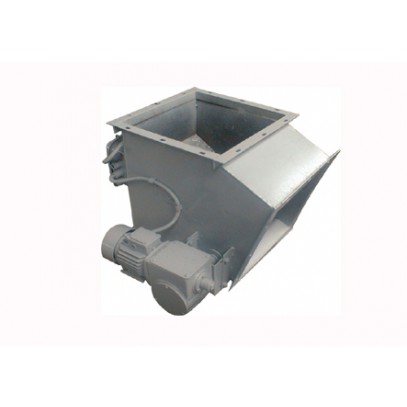
Flap valve with electric drive У10-КП are designed to switch the flow of grain and products of its processing in the gravity system
The main parameters and dimensions of the У10-КП-1 flap valves are shown in the table:
| № | Options | Unit of measure | Value | ||||||
| У10-КП-1-200 | У10-КП-1-250 | У10-КП-1-300 | У10-КП-1-320 | У10-КП-1-350 | У10-КП-1-400 | У10-КП-1-450 | |||
| 1 | Through hole diameter | mm | 200 | 250 | 300 | 320 | 350 | 400 | 450 |
| 2 | Flange outer diameter | mm | 290 | 340 | 390 | 410 | 440 | 490 | 540 |
| 3 | Dimensions | ||||||||
| - length | mm | 565 | 665 | 680 | 830 | 905 | 1025 | 1135 | |
| - width | mm | 450 | 500 | 686 | 570 | 600 | 650 | 700 | |
| - height | mm | 380 | 465 | 495 | 585 | 635 | 720 | 805 | |
| 4 | Weight (no more) | kg | 38 | 42 | 49 | 49 | 50 | 52 | 56 |
| 5 | Switching time | sec | 1 | ||||||
| 6 | Rated voltage | V | 380 | ||||||
| 7 | Power consumption of the electric drive | kWt | 0,25 (Gear motor) | ||||||
| 8 | Life time | years | 10 | ||||||
The main parameters and dimensions of the У10-КП-2 flap valves are shown in the table:
| № | Options | Unit of measure | Value | ||||||
| У10-КП-2-200 | У10-КП-2-250 | У10-КП-2-300 | У10-КП-2-320 | У10-КП-2-350 | У10-КП-2-400 | У10-КП-2-450 | |||
| 1 | Through hole diameter | ||||||||
| - length | mm | 200 | 250 | 300 | 230 | 250 | 400 | 450 | |
| - width | mm | 200 | 250 | 300 | 320 | 350 | 400 | 450 | |
| 2 | Angle | degree | 30-45 | ||||||
| 3 | Dimensions | ||||||||
| - length | mm | 490 | 540 | 697 | 615 | 640 | 690 | 740 | |
| - width | mm | 460 | 510 | 688 | 580 | 610 | 660 | 710 | |
| - height | mm | 600 | 650 | 666 | 780 | 850 | 970 | 1460 | |
| 4 | Weight (no more) | kg | 35 | 41 | 54 | 51 | 53 | 56 | 58 |
| 5 | Switching time | sec | 1 | ||||||
| 6 | Rated voltage | V | 380 | ||||||
| 7 | Power consumption of the electric drive | kWt | 0,25 (Gear motor) | ||||||
| 8 | Life time | years | 10 | ||||||
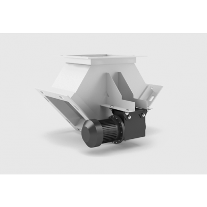
The valve is supplied assembled according to the assembly drawing.
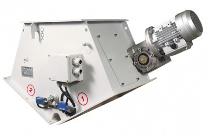
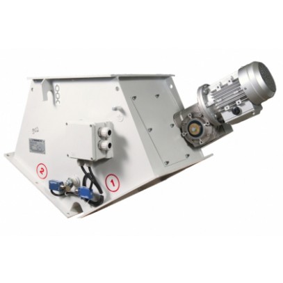
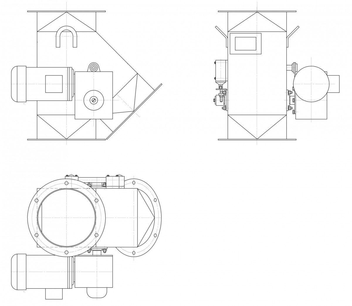
The device of a rocker valve with an electric drive of the У10-КП brand and its operating principle is as follows.
A drive shaft is inserted into a metal sheet steel valve body on slide bearings, a gate is attached to the shaft using bolts.
On the side surfaces of the case, on one side, a drive is attached, on the other - two ВП-15 travel switches. The drive is connected to the valve shaft. On the other end of the shaft there is a rocker arm with adjusting screws designed to turn off the drive when the gate is turned to the end position. Grain flows by gravity into the intake part of the valve. Depending on the location of the gate in the valve body, the direction of the grain flow to the right or left branch of gravity changes.
Contact us