Mon-Fri 8: 00-17: 00, break 12: 00-13: 00, Sat-Sun: closed
- Main
- Elevator equipment
- Fire-resistant gate
- Fire barrier ЗО
Fire barrier ЗО
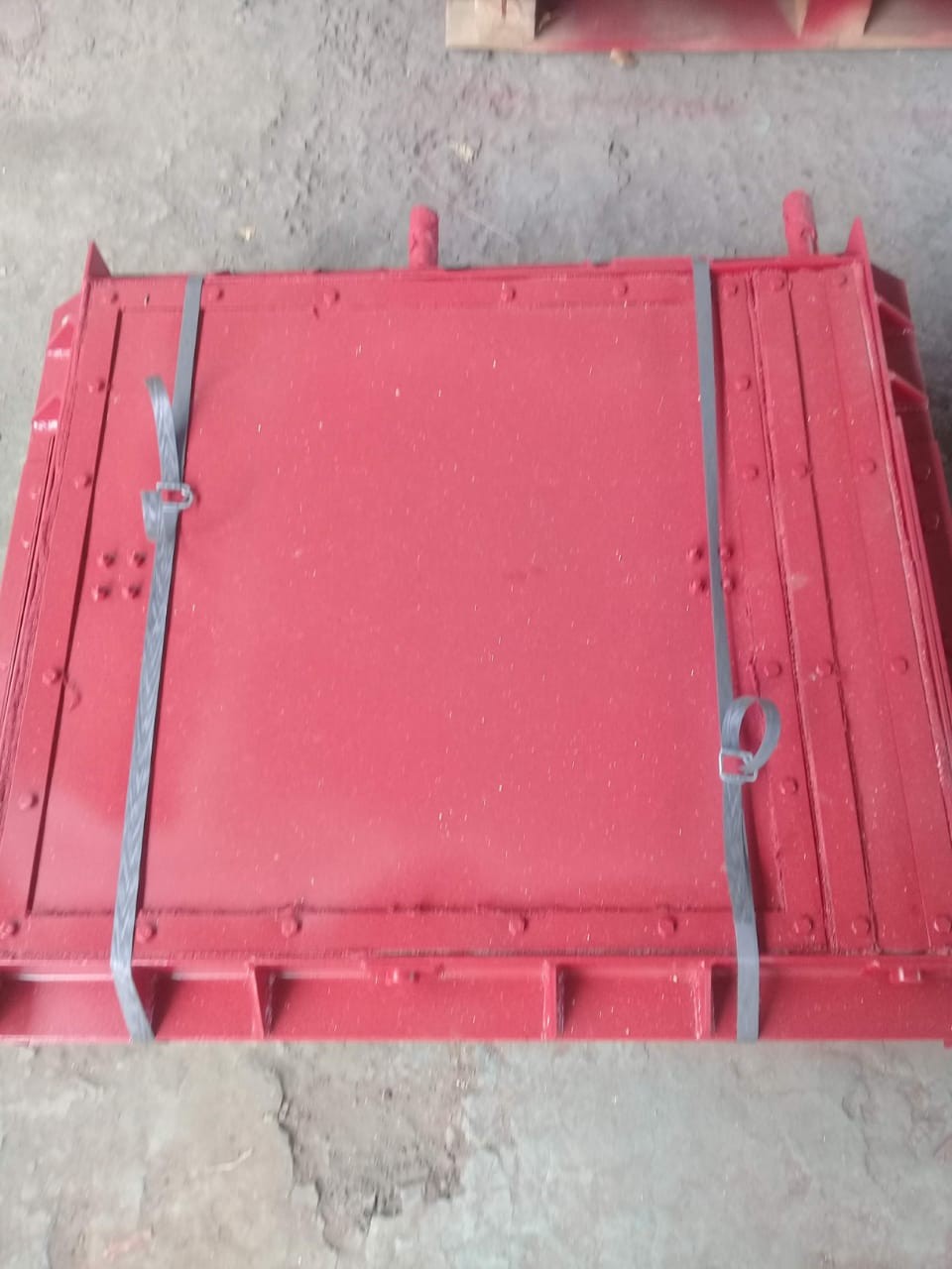
Fire shutter ЗО is designed for automatic shutdown of technological openings in the walls of seed cleaning complexes and workshops for primary processing of grain in the event of a fire in one of its compartments.
The valve meets the requirements of climatic modification U, placement category 3 in accordance with GOST 15150.
| № | Name parameter | Unit of measure | Type | ||||||
| ЗО - 600*600 | ЗО - 600*1105 | ЗО - 750*875 | ЗО - 750*1205 | ЗО - 900*1025 | ЗО - 900*1230 | ЗО - 1100*1225 | |||
| 1 | Working section size, no more | ||||||||
| - width | mm | 600 | 600 | 750 | 750 | 900 | 900 | 1100 | |
| - height | mm | 600 | 1105 | 875 | 1205 | 1025 | 1230 | 1225 | |
| 2 | Fire resistance limit, not less | h | 1,2 | ||||||
| 3 | Response time, no more | sec | 2,5 | ||||||
| 4 | Overall dimensions (without rope), no more | ||||||||
| - length | mm | 1450 | 1450 | 1450 | 1450 | 1450 | 1450 | 1450 | |
| - width | mm | 850 | 850 | 1000 | 1000 | 1150 | 1150 | 1350 | |
| - height | mm | 1300 | 1300 | 1300 | 1500 | 1300 | 1500 | 1520 | |
| 5 | The gap between the flange and the damper, no more | mm | 10 | ||||||
| 6 | Weight, no more | kg | 230 | 315 | 315 | 360 | 370 | 415 | 460 |
Product structure and delivery set
- fire retardant bolt
- accessory kit
- passport
It is allowed to complete a batch with one passport. A batch should be considered the number of locks obtained from one document, but not more than 10 pieces.
The shutter consists of two flanges 1 and 31, two shutters 5 and 29. Shutters 5 and 29 are located between the working and idle branches of the conveyor belt. Gear 3 is mounted on the damper axis 5, which meshes with the gear 4. The gear 4 is rigidly connected to the lever 6. The lever 28 is fixed on the damper axis 29. Weights 11 and 23 are suspended on the levers 6 and 28. The kinematic connection between the dampers 5 and 29 is carried out using two rods 2 and 30, the end of which is fixed closer to the periphery of the flaps. Levers 6 and 28 with weights 11 and 23 suspended from them are held in a vertical position by levers 9 and 25. Levers 9 and 25 contact with levers 6 and 28 through stops 10 and 24. The pivot axes of levers 9 and 25 are located on brackets 7 and 27 . Ropes 12 and 22 with thermal locks 13 and 21, suspended on rollers 14 and 20 and loaded with counterweights 15 and 19 with rails 16 and 18 are attached to the levers 9 and 25.
On brackets 7 and 27, switches 8 and 26 are installed, the rollers of which are pressed by levers 6 and 28. The ropes 12 and 22 include manual starting devices 32 and 33. Flanges 1 and 31 are mounted to the fire wall with studs 17.
The principle of operation of the gates is to break the ropes 12 and 22 due to the actuation of the thermal lock 13 and 21 under the influence of an increase in temperature in the event of a fire or due to the operation of manual starting devices 32 and 33.

Contact us